Single Phase Igbt Inverter Circuit Diagram
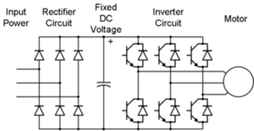
120° mode inverter – circuit diagram, operation and formula Circuit schematic of igbt module 12+ 3 phase igbt inverter circuit diagram
Three Phase Inverter : Circuit, Working and Its Applications
Three phase inverter schematic Power circuit diagram of an igbt based single phase full-bridge Sic/igbt 3 phase inverter development kit
Inverter phase circuit pwm bridge full power diagram three schematic switching voltage controlled
Igbt circuit module schematic fig4Inverter phase circuit schematic igbt 3-phase pwm power inverter circuitInverter phase igbt electronics.
12+ 3 phase igbt inverter circuit diagramVfd pwm igbt inverter rangkaian vsd skema induksi kecepatan trafo wiring frecuencia pengaturan mesin control vfds firing variador esquema circuits Three phase inverter : circuit, working and its applicationsInverter igbt sic vfd spm taraz inverters dc leistungselektronik converters.
![Pengaturan Kecepatan Motor Induksi Dengan Inverter VFD atau VSD](https://1.bp.blogspot.com/-EtkkPTITC7M/WnRQ25INb1I/AAAAAAAAGpM/-11bFIgspOwyhe56H7Affvj1LfmmSPE0wCLcBGAs/s1600/skema%2Binverter.jpg)
Inverter igbt power diagrams diode supply
Inverter igbtIgbt inverter pwm switching frequency Pengaturan kecepatan motor induksi dengan inverter vfd atau vsd12+ 3 phase igbt inverter circuit diagram.
Inverter circuit diagram 120 mode operation phase three bridge power formula figure shown below electrical .
![120° Mode Inverter – Circuit Diagram, Operation and Formula](https://i2.wp.com/electricalbaba.com/wp-content/uploads/2020/09/circuit-diagram-of-three-phase-bridge-inverter.jpg)
![SiC/IGBT 3 Phase Inverter Development Kit | Taraz Technologies](https://i2.wp.com/www.taraztechnologies.com/wp-content/uploads/2020/02/SPM-VFD-v2.png)
![Power circuit diagram of an IGBT based single phase full-bridge](https://i2.wp.com/www.researchgate.net/profile/Hassan-M-Abdar/publication/261459665/figure/fig1/AS:296938747514883@1447807122790/Power-circuit-diagram-of-an-IGBT-based-single-phase-full-bridge-inverter.png)
![12+ 3 Phase Igbt Inverter Circuit Diagram | Robhosking Diagram](https://i2.wp.com/www.electronics-tutorial.net/wp-content/uploads/2015/09/inverter24.png)
![3-Phase PWM Power Inverter Circuit](https://i2.wp.com/www.powerinverter.org/image/voltage-type-three-phase-full-bridge-inverter-structure-4501.jpg)
![12+ 3 Phase Igbt Inverter Circuit Diagram | Robhosking Diagram](https://i2.wp.com/img.alicdn.com/imgextra/i3/6000000000783/TB2W6QeCMaTBuNjSszfXXXgfpXa_!!6000000000783-0-tbvideo.jpg)
![Circuit schematic of IGBT module | Download Scientific Diagram](https://i2.wp.com/www.researchgate.net/profile/Xiaobing_Luo4/publication/261076220/figure/fig4/AS:392447415865349@1470578163679/Circuit-schematic-of-IGBT-module.png)
![Three Phase Inverter Schematic | Download Scientific Diagram](https://i2.wp.com/www.researchgate.net/profile/Luca_Sani/publication/269255065/figure/download/fig6/AS:300043929178116@1448547455253/Three-Phase-Inverter-Schematic.png)
![12+ 3 Phase Igbt Inverter Circuit Diagram | Robhosking Diagram](https://i2.wp.com/ai2-s2-public.s3.amazonaws.com/figures/2017-08-08/925e1b3d2c8359e95ce6dda69b353fcf538ccd6a/3-Figure4-1.png)
![Three Phase Inverter : Circuit, Working and Its Applications](https://i2.wp.com/www.elprocus.com/wp-content/uploads/Three-Phase-Inverter-Circuit.png)